Product Overview
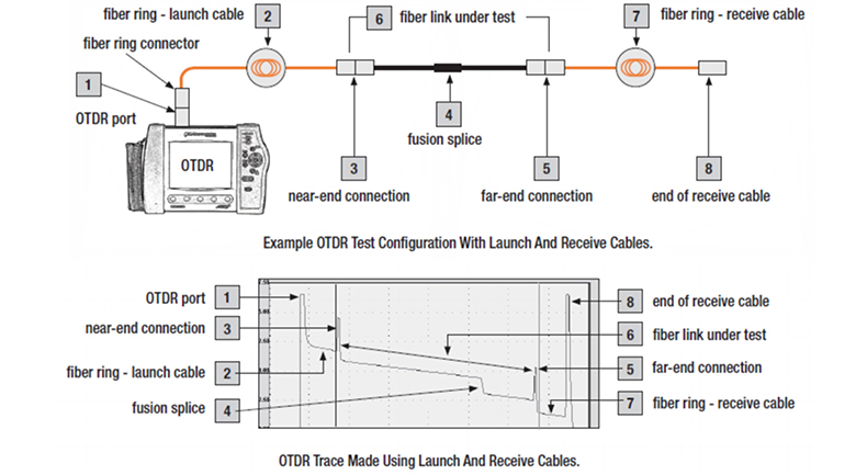
Measuring an insertion loss of the near-end and / or far-end connection of a fiber optic link with an OTDR requires a launch and / or receives test cable. A launch cable, which connects the OTDR to the link under test, reveals the insertion loss and reflectance of the near-end connection. A receive cable, which connects to the far-end of the link, reveals the insertion loss and reflectance of the far-end connection. Launch and receive test cables can range from 1 km to 2 km (or longer) in length. Because very long test cables are impractical to transport and use, FCST offers coiled lengths of 50 um multimode, 62.5 um multimode, or single-mode fiber packaged in compact rings. Fiber Rings of 1000 m of fiber are ideal for premises fiber network test applications. Fiber Rings of 1 km and 2 km of single-mode fiber are designed for broadband, long-haul fiber network test applications.
OTDR Launch Cable Models
| Type # | Length(km) | Fiber Type |
|---|---|---|
| FCST1-SM-1KM-y1-y2 | 1 km | Single-Mode, 9/125 um |
| FCST1-M5-1KM-x1-x2 | 1 km | Multi-Mode, 50/125 um |
| FCST1-M6-1KM-x1-x2 | 1 km | Multi-Mode, 62.5/125 um |
| FCST1-SM-2KM-y1-y2 | 2 km | Single-Mode, 9/125 um |
| FCST1-M5-2KM-x1-x2 | 2 km | Multi-Mode, 50/125 um |
| FCST1-M6-2KM-x1-x2 | 2 km | Multi-Mode, 62.5/125 um |
Carrying Case Color: Orange / Gray or Black, Case color depends on stock information.
x1, x2 — connectors for multimode cables, specify type [ST, SC, FC, LC, E2000, Angled SC, Angled FC, Angled LC, Angled E2000].
y1, y2 — connectors for single-mode cables, specify type [ST, SC, Angled SC, FC, Angled FC, LC, Angled LC, E2000 or Angled E2000].Other connector types, fiber types, and fiber lengths will be quoted upon request.
How To Generate A Baseline Trace Using Fiber Rings
Example OTDR Test Configuration With Launch And Receive Cables
